Turbochef-technologies TurboChef User Manual
Browse online or download User Manual for Microwaves Turbochef-technologies TurboChef. TurboChef Technologies TurboChef User Manual
- Page / 94
- Table of contents
- BOOKMARKS
- TurboChef Service Manual 1
- For further information call: 2
- +1 214.379.6000 2
- NEVER attempt to 3
- Table of Contents 4
- IMPORTANT SAFETY INSTRUCTIONS 7
- GENERAL SAFETY INFORMATION 7
- REDUCING FIRE RISK 7
- EXCESSIVE MICROWAVE ENERGY 8
- GROUNDING INSTRUCTIONS 8
- POWER CORD REPLACEMENT 8
- 1 year parts and labor 10
- VAC, 60 Hz, 1 phase 10
- 4” (102 mm) adjustable legs 10
- 304 stainless steel line 10
- POWER INPUT 11
- TURBO / +1 214.379.6000 13
- 1 2 3 4 5 14
- Theory of Operation 15
- THEORY OF OPERATION 16
- CONTROL SYSTEM 16
- MICROWAVE SYSTEM 16
- CONVECTION SYSTEM 16
- BOTTOM IR AND CCV 16
- Fault Codes 19
- TO VIEW FAULT CODES 20
- FAULT CODE DEFINITIONS 20
- FAULT CODES 21
- The Control System 22
- CONTROL 23
- TEST MODE 24
- TEST FUNCTION OPTIONS 25
- W) status indicator is not 26
- DIAGNOSTIC MODE 26
- (CCSP) 26
- THE CONTROL SYSTEM 27
- FIGURE 15: Done Screen 28
- CONTROL SYSTEM PANEL PARTS 30
- ISSUE RESOLUTION 31
- 800.90TURBO 33
- The Microwave System 34
- MONITOR CIRCUIT DESCRIPTION 35
- MICROWAVE SYSTEM PARTS 36
- THE MICROWAVE SYSTEM 37
- MICROWAVE SYSTEM COMPONENTS 38
- WAVE GUIDE COVER REPLACEMENT 39
- WAVE GUIDE REPLACEMENT 40
- REPLACEMENT 40
- FIGURE 24: High Voltage Diode 42
- FIGURE 25: Magnetron 42
- The Oven Door 47
- OVEN DOOR PARTS 48
- ADJUSTING THE OVEN DOOR 49
- ADJUSTMENTS AND PARTS 50
- MONITOR SAFETY SWITCH PARTS 51
- = 0.020” 51
- Old Switch Setup 52
- New Switch Setup 53
- FIGURE 35: Oven Door Assembly 55
- PART TORQUE 56
- SCREW TORQUE CHART 56
- The Convection Circuit 58
- CONVECTION CIRCUIT COMPONENTS 59
- THE CONVECTION CIRCUIT 60
- IR Element and Catalytic 63
- Converter 63
- COMPONENTS 64
- Schematics and Schematic 66
- Components 66
- SCHEMATIC PARTS 67
- TEST POINT LOCATIONS 67
- I/O BOARD SCHEMATIC 68
- 41: NGC (Tornado) Schematic 69
- NGC (UK) SCHEMATIC 70
- 43: NGCEW (Tornado) Schematic 71
- 44: NGCED (Tornado) Schematic 72
- NGC (BRAZIL) SCHEMATIC 73
- Service Parts and 74
- Illustrations 74
- FILAMENT AND 79
- HIGH VOLTAGE 79
- TERMINALS 79
- APPLY HI-TEMP 81
- GREASE TO AREA 81
- FIGURE 35: OVEN DOOR ASSEMBLY 83
- TURBO or +1 214-379-6000 85
- Comprehensive Part List 89
- ITEM DESCRIPTION 90
- +1 214-379-6000 94
Summary of Contents
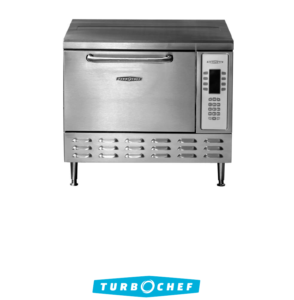
Accelerating the World of CookingTurboChef Service ManualFOR THE TURBOCHEF NGC (TORNADO) OVEN800.90TURBOPart Number: NGC-1007 / Revision D / September
Standard FeaturesRecirculating airpath with patented catalytic convertersystemMulti-speed convection blowerIndependently-controlled bottom browning
2INSTALLATION, SPECIFICATIONS, AND MAINTENANCENOTE: The Smart Voltage Sensor Technology doesnot compensate for lack of voltage or over-voltagesituatio
If installation must be “built in,” the operator mustensure the following:Minimum of 300 cfm (8.5 cmm) of supplement flowwithin the cabinet.Minimum
4Oven Restraint Kit (TC3-0242 KIT)The Oven Restraint Kit is an optional system thathelps prevent the oven from moving forward duringuse and/or cleanin
INSTALLATION, SPECIFICATIONS, AND MAINTENANCE5DAILY MAINTENANCE FOR THE NGCBefore cleaning, check with the store for customcleaning instructions.When
Theory of Operation
THEORY OF OPERATION7THEORY OF OPERATIONThe TurboChef NGC (Tornado) oven utilizesthree independent heat transfer mechanisms torapidly cook food. The sy
THEORY OF OPERATION8GLOSSARY OF COMMON OPERATING TERMSOff StateAll the oven’s control systems are off and the cook cavity temperature is below 150ºF (
THEORY OF OPERATION9KeypadThe primary interface for the operator.DisplayDisplays all visual information to the operator. Self-Test (STEST)A special di
Fault Codes
For further information call:800.90TURBO+1 214.379.6000Accelerating the World of Cooking
11The NGC (Tornado) oven has the ability to continuallymonitor and log various fault conditions. Some faultconditions will terminate cook cycles, whil
FAULT CODES12NOTE: Door interlock switches are in parallel. SeeOVEN SCHEMATICS, pages 55-63. The fault is moni-tored during a cook cycle, or in SELF T
The Control System
THE CONTROL SYSTEMThe Control System is comprised of the componentsthat signal, sense, command, and switch the oven’svarious components. Figure 7 show
THE CONTROL SYSTEM14CONTROL SYSTEM COMPONENT DESCRIPTIONS24 VDC Power Supply24 VDC output at 40 watts. Supplies controlvoltage for I/O control board,
THE CONTROL SYSTEMTo enter TEST MODE (Figure 8):1. Press the BACK key until the display is in the OFFSTATE.2. Simultaneously press BACK and ENTER keys
THE CONTROL SYSTEM16Diagnostic Display (Screen 2)The DIAG key turns on or off the diagnostic displayfeature. When this feature is enabled, the oven wi
To change the cook cavity temperature (CCSP),press the UP and DOWN keys. Temperature rangesvary depending on software. Once you have selectedthe corre
Loading a Menu from a Smart Card1. Ensure the oven is in the OVEN OFF/COOLINGDOWNmode.2. Enable the LOAD MENUfunction (page 19). The oven will return
USER CONFIGURABLE OPTIONS - ENABLE/DISABLE CODESThe following codes enable and disable each function/screen listed. They do not take you to the functi
IMPORTANT SAFETY INFORMATION - PLEASE READ FIRSTWARNING: Improper installation, adjustment, alteration, service, or maintenance can cause property dam
FIGURE 17: Control System Panel Enclosure and PartsCONTROL SYSTEM PANEL PARTSFigure 17.1. NGC-1040 Cover, Keypad/Display, StdNGC-1209 Cover, Keypad/Di
ISSUE RESOLUTIONNo Display (Blank) 1. Verify power 208 VAC or 240 VAC is going to the oven correctly. If not, correct the voltage supply. 2. Control D
ISSUE RESOLUTIONF1: Blower RunningStatus BadMotor not running when commanded. 1. Status Indicator “A” is highlighted/backlit in TEST MODE. Verify 208
ISSUE RESOLUTIONF2: Cook TemperatureLow 1. Verify the high-limit thermostat is not tripped. If high-limit is tripped, reset and allow the oven to war
The Microwave System
THE MICROWAVE SYSTEM25The Microwave System is the most complex system inthe oven. Proper care must be taken during servicingto protect both the operat
+(B)-(C)(A)-4800 VMAGNETRON VOLTAGE0-+-+24002400VDC4800VDCCurrentFlowTRANSFORMER OUTPUT VOLTAGE+(B)0-(C)(A)-2400 V+2400 V--++2400VDC2400CurrentFlowCAP
13. 100481 High Voltage Diode (x2)14. Mag Fan Relay, GenericNGC-3030-1 North AmericaNGC-3030-4 Europe, Asia-Pacific MultiphaseNGC-3030-7 Europe Single
MICROWAVE SYSTEM COMPONENTSBelow is a description of each component withinthe Microwave System.MagnetronMagnetrons supply the RF energy at 2.45 GHzand
FIGURE 22: Wave Guide Cover/Wave Guide Removal and ReplacementTo determine software type,1. Make sure the oven is in the COOLINGDOWN/OVEN OFF mode.2.
Important Safety Instructions iGeneral Safety Information iReducing Fire Risk iPrecautions to be Observed Before and During Servicing to Avoid Possibl
4. Using acetone, clean the oven floor where thenew wave guide cover will sit. 5. Apply a 1/8” diameter bead of high temperatureRTV (included with Ite
high-voltage transformers are most likely wired in-phase. As a last check, energize the MicrowaveSystem and verify the voltages between the taps oneac
THE MICROWAVE SYSTEM325. While holding the MGTRON soft key, move the sur-vey meter around the outline of the oven door,keeping the tip of the meter in
THE MICROWAVE SYSTEM33HIGH VOLTAGE TRANSFORMERS PRIMARY VOLTAGE, FREQ, TAPS, AND RESISTANCESECONDARY TAPS AND RESISTANCENGC-3062-1 208 VAC, 60 Hz, 1 &
ISSUE RESOLUTIONMagnetron Troubleshooting GuidelinesWARNING: Never test the secondary voltages. Voltage on this side of thecircuit is lethal, reaching
ISSUE RESOLUTIONF3: Magnetron Current Low (cont.)WARNING: Never try to check the secondary voltages of the High Voltage Transformers.With the top cov
ISSUE RESOLUTIONF3 Fuse Blown, cont. c. Monitor circuit fault: Verify operation of all interlock switches. In addition, check the Fault Log. If the mo
The Oven Door
The proper fit and adjustment of the oven door isessential for safe and reliable operation of the NGC(Tornado) oven. The oven door provides three prim
ADJUSTING THE OVEN DOORWARNING: Procedure should be done while oven is hot. As a result, exercise extreme caution when adjusting the door.1. Open the
Oven Options 18User Configurable Options - Enable/Disable Codes 19User Configurable Options - Access Codes 19Control System Panel Parts 20Control Syst
FIGURE 27: Mis-adjusted Oven DoorFIGURE 28: Mis-adjusted Oven Door3. Open and close the door several times to ensure itcloses smoothly and the door ac
FIGURE29: Correct Primary and Secondary InterlockAdjustment and Parts - Old Switch SetupDOOR SWITCH ASSEMBLY AND PARTSFigure 30, next page53. NGC-1072
FIGURE 31: Monitor Switch Adjustment and Assembly - Old Switch SetupFIGURE 30: Door Switch Assembly and Parts - Old Switch Setup5861571536359546055622
ADJUSTING THE PRIMARY INTERLOCK SWITCH -NEW SWITCH SETUPThe new switch assembly is identifiable by the pri-mary switch being located on the left side
ADJUSTING THE SECONDARY AND MONITORINTERLOCK SWITCHES - NEW SWITCH SETUP1. Disconnect power to the unit.2. Disconnect the 40-pin connector from the I/
PRECAUTIONS FOR SAFE USE TO AVOID POSSIBLEPRECAUTIONS A AFIN D'EVITER UNE EXPOSITIONEXPOSURE TO EXCESSIVE MICROWAVE ENERGY1. S'il y a un obj
SHUNT CAVITY/PLATETightening SequenceSHUNT ASSY/DOOR COVERTightening Sequence5841591110 62371214151316148115910166237171112134FIGURE 36: Oven Door Ass
INTERLOCK SWITCH TROUBLESHOOTINGISSUE RESOLUTION“Cook Door Open”MessageDetermine which interlock switch is open. Access TEST MODEto viewinterlock swit
The Convection Circuit
THE CONVECTION CIRCUIT47The Convection Circuit provides the high-temperatureairflow required to brown and cook food items.CONVECTION CIRCUIT COMPONENT
Chapter 7: The Convection CircuitConvection Circuit Components 47Convection Circuit/Blower Motor Parts 48Convection Circuit Troubleshooting 49Motor Wi
NOTICE:This device complies with Part 18 of the FCC Rules.Operation is subject to the following conditions:1. This device may not cause harmful interf
ISSUE RESOLUTIONF8: Heat LowOven Not Warming Up1. Check that the blower motor is moving air.Blower motor is not moving air: Check blower motor assemb
ISSUE RESOLUTIONF1: Blower RunningStatus Bad1. Verify motor spins freely.Motor seized: Unplug oven and correct obstruction or replace motor.Motor sp
IR Element and CatalyticConverter
The IR Element and Catalytic Converter provide twovery different, but essential functions.The IR element provides the bottom browning -similar to a re
Removing and Installing the Catalytic Converter 1. Unplug the oven.2. Remove the IR element. (See above procedure.)3. Once the IR element has been rem
Schematics and SchematicComponents
FIGURES 40 THRU 45: NGC OVEN SCHEMATICSFigure 40 I/O Board SchematicFigure 41 NGC US SchematicFigure 42 NGC UK SchematicFigure 43 NGC EW SchematicFigu
I/O BOARD SCHEMATIC54FIGURE40: I/O Control Board and Test Point Locations
K6-B (VOLTS MOD OUT) 29 29P4P6J6J4IRCC4039THERMOCOUPLES EC373638BMSC (4) (COM RTN) 32343335BMSC (3) (ENABLE OUT) 31K4 (B-) (CONV OUT) 30C(+)IRA(-)C(+)
iINTRODUCTIONIMPORTANT SAFETY INSTRUCTIONSStrictly adhere to the following safety precautions to reduce the risk of:BurnsElectric shockFireInjury
D2 D1MAG 1 MAG 2FT2FT1BL 14BL 15RED 6RED 5D O NOT USEWH-29NCCCOR-62SAFETY INTERLOCKS - NEW SETUPNCINTERLOCKPRIMARYMONITOR SWITCHCNCNOSECONDARYBK-22BK-
K7 MAG FAN RELAY 29 29P4P6J6J4IRCC4039THERMOCOUPLESEC373638BMSC (4) (COM RTN) 32343335BMSC (3) (ENABLE OUT) 31K4 (B-) (CONV OUT) 30C(+)IRA(-)C(+)CC403
K7 MAG FAN RELAY 29 29P4P6J6J4IRCC4039THERMOCOUPLES EC373638BMSC (4) (COM RTN) 32343335BMSC (3) (ENABLE OUT) 31K4 (B-) (CONV OUT) 30C(+)IRA(-)C(+)CC40
FIGURE45: NGC Brazil (Tornado) SchematicNGC (BRAZIL) SCHEMATIC63
Service Parts andIllustrations
SERVICE PARTS AND ILLUSTRATIONS65FIGURE 7: NGC (TORNADO) CONTROL SYSTEMChapter 4: The Control System - Page 13GROUNDSTATUS OKI/O COM12OUT240 VAC3 PHAS
SERVICE PARTS AND ILLUSTRATIONS66FIGURE 17: CONTROL SYSTEM PANEL ENCLOSURE AND PARTSChapter 4: The Control System - Page 20CONTROL SYSTEM PANEL PARTSF
67SERVICE PARTS AND ILLUSTRATIONSFIGURE 18: MONITOR CIRCUIT - SHOWN IN FAILSAFE STATEChapter 5: The Microwave System - Page 2579AB14361212CDPNCNO79AB1
29313032333435363768SERVICE PARTS AND ILLUSTRATIONSFIGURE 21: MICROWAVE SYSTEM PARTSChapter 5: The Microwave System - Page 27Microwave System Parts24.
SERVICE PARTS AND ILLUSTRATIONSFIGURE 24 & 25: HIGH VOLTAGE DIODE AND MAGNETRONChapter 5: The Microwave System - Page 3269ANTENNAFFAFILAMENT AND H
iiINTRODUCTIONPRECAUTIONS TO BE OBSERVED BEFORE AND DURING SERVICING TO AVOID POSSIBLE EXPOSURE TOEXCESSIVE MICROWAVE ENERGY(a) DO NOT operate or allo
70Primary and Secondary Interlock Switch Parts47. NGC-1076-2 Actuator, Door48. 102809 Screw, #8-32 x 3/8” 100Þ CSK49. 102921 Screw, #8-32 x 3/8”50. 1
SERVICE PARTS AND ILLUSTRATIONS71Monitor Safety Switch Parts64. 102804 Hinge, Right65. 102012 Switch, Limit, Micro66. NGC-1126 Plate, Door Switch67. 1
72SERVICE PARTS AND ILLUSTRATIONS798082x283x278818277808281FIGURES 33 AND 34: SECONDARY AND MONITOR SWITCH ADJUSTMENT AND ASSEMBLY - NEW SWITCH SETUPC
SERVICE PARTS AND ILLUSTRATIONS73Oven Door Parts84. NGC-3067* Door, NGC, Generic*NGC-3067-2* Door, NGC, SBK*85. NGC-3021 Kit, Shunt Plate86. NGC-1061
FIGURE 37: CONVECTION CIRCUIT BLOCK DIAGRAMChapter 7: Convection Circuit - Page 47BMSCBLWRMTRM4 GREENM3 WHITEM2 REDM1 BLACK4321240 VAC3 PHASE OUT200-2
SERVICE PARTS AND ILLUSTRATIONS75Convection Circuit Parts102. 101688 Screw, #8 x 1/2” PTH103. NGC-1081 Cover, Motor104. 100906 Nut, 1/4”-20, Flange105
IR Element and Catalytic Converter Parts116. 101312 Snap Ring117. 102449 Washer, Shim118. NGC-3003 IR Element119. NGC-1116 Shield, Microwave120. 10168
SERVICE PARTS AND ILLUSTRATIONS77-HOT-CAUTIONshock, connect to properly grounded outlets only.electrique branchez seulement a une prise Pour assurer p
78SERVICE PARTS AND ILLUSTRATIONS-HOT-CAUTIONshock, connect to properly grounded outlets only.electrique branchez seulement a une prise Pour assurer p
Comprehensive Part List
Installation, Specifications, and Maintenance
ITEM DESCRIPTIONPART NUMBER FIGURE NUMBER (PAGES 65-78)Actuator, Door NGC-1076-2 29, 35Assembly, Keypad/Housing, Cover, Standard NGC-1054-1 46Assembly
ITEM DESCRIPTIONPART NUMBER FIGURE NUMBER (PAGES 65-78)Fan Blade, Motor NGC-3007 38Fan, Magnetron Cooling 100083 20Filter, EMI, 1Ph (USA, Europe, Lati
ITEM DESCRIPTIONPART NUMBER FIGURE NUMBER (PAGES 65-78)Nut, Flange, 1/4-20 100906 38Nut, M5, Yellow Zinc (Magnetrons, Bottom Electrical Plate) 100101
ITEM DESCRIPTIONPART NUMBER FIGURE NUMBER (PAGES 65-78)Shim, 0.030 NGC-1169-1 32Shim, 0.045 NGC-1169-2 32Shim, Door Latch NGC-1132 35Shim Tool, 0.030
For further information call:800.90TURBO or+1 214-379-6000Accelerating the World of CookingHeadquartersSix Concourse ParkwaySuite 1900 Atlanta, Georgi
Related products and manuals for Microwaves Turbochef-technologies TurboChef
 (34 pages)
© 2020, manymanuals.com. All rights reserved. | 7.280 s |
 Manymanuals.com
 Manymanuals.de
 Manymanuals.fr
 Manymanuals.it
 Manymanuals.pl
 Manymanuals.cz
 Manymanuals.es
 Manymanuals-pt.com
Comments to this Manuals